¶ Overview
The auctoria Rocks is a powerful AI-generated modeling tool that allows you to create a custom 3D rock model precisely suited to your needs.
¶ Introduction to the Rocks Building Module with a Simple Example (low-resolution method)
Building a rock using the Rocks module in the low-resolution method can be done very quickly in just a few steps (details will be discussed in the following sections). This method involves a reconstruction step and works best with single, connected elements; while it doesn’t support completely separate disconnected boxes, nearby elements can be merged automatically. It produces closed meshes without holes, with the algorithm able to close small gaps when needed. The process is optimized for objects with regular proportions, so extremely tall or irregularly sized shapes might be more challenging to generate.
¶ Segment Map
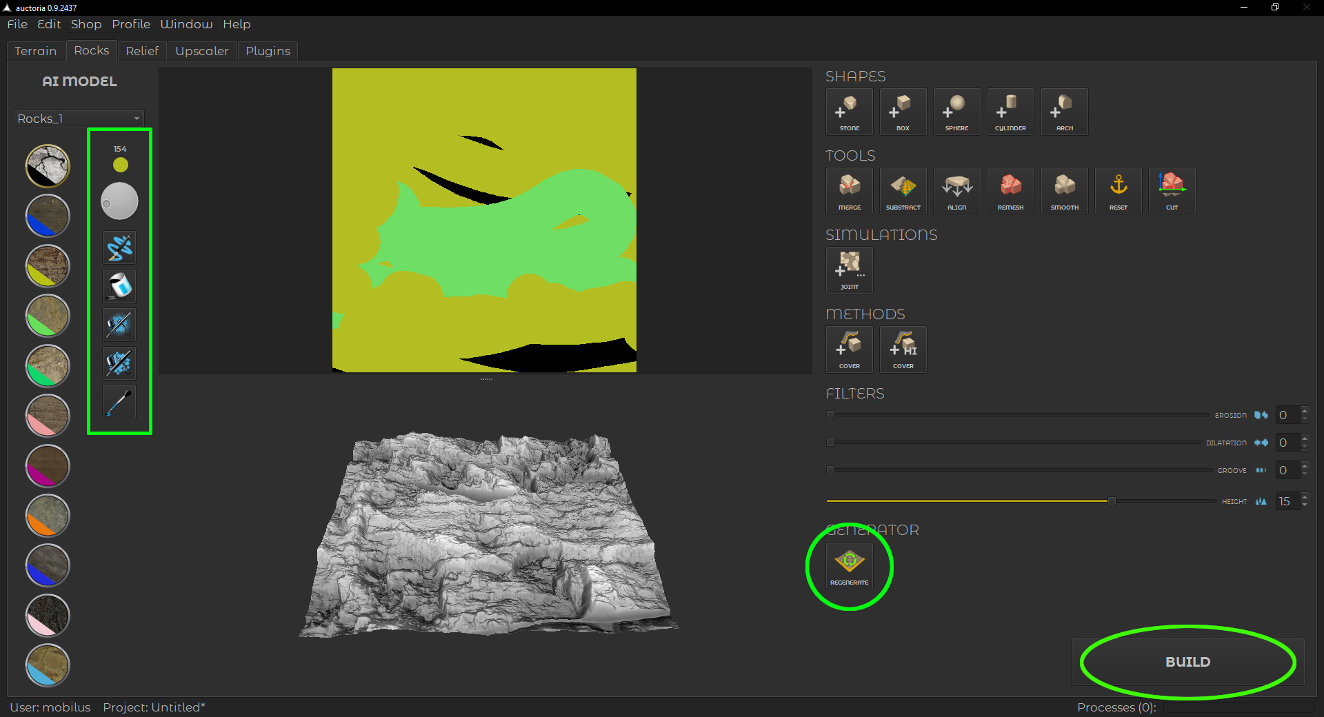
First, we prepare the Segment Map, and then we click the REGENERATE button. The outcome of these steps is displayed in the image below.
¶ Rock Generator
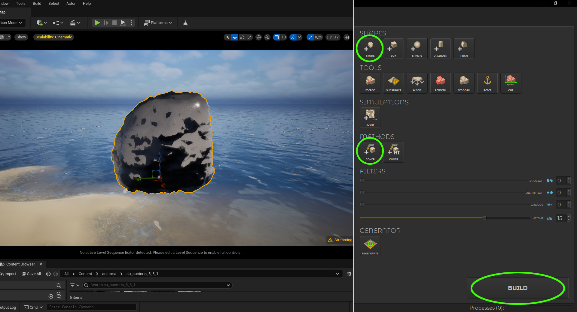
If we already have a prepared rock sample, we can add a base shape (STONE button in the SHAPES section), add a cover (COVER button in the METHODS section), and then click the BUILD button.
Of course, it is possible — and even recommended — to use the tools in a top-to-bottom order: add STONE, add COVER, paint the Segment Map, click REGENERATE, and finally click BUILD.
¶ Build Rock
Depending on the selected method, the BUILD button may display an additional settings window — this is the case when using the Cover Method with rocks.
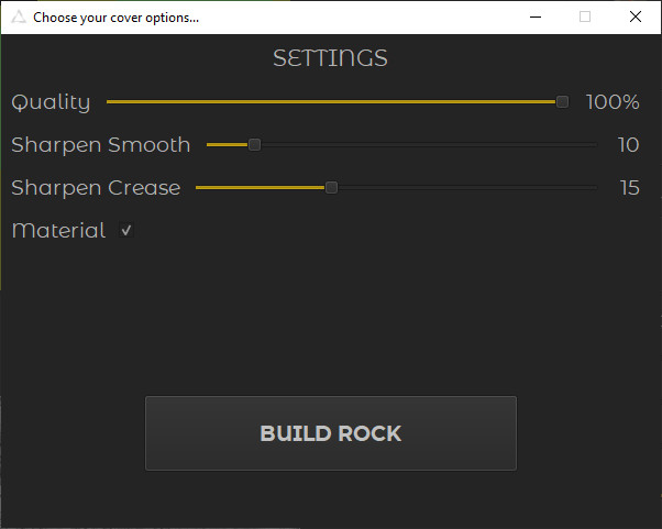
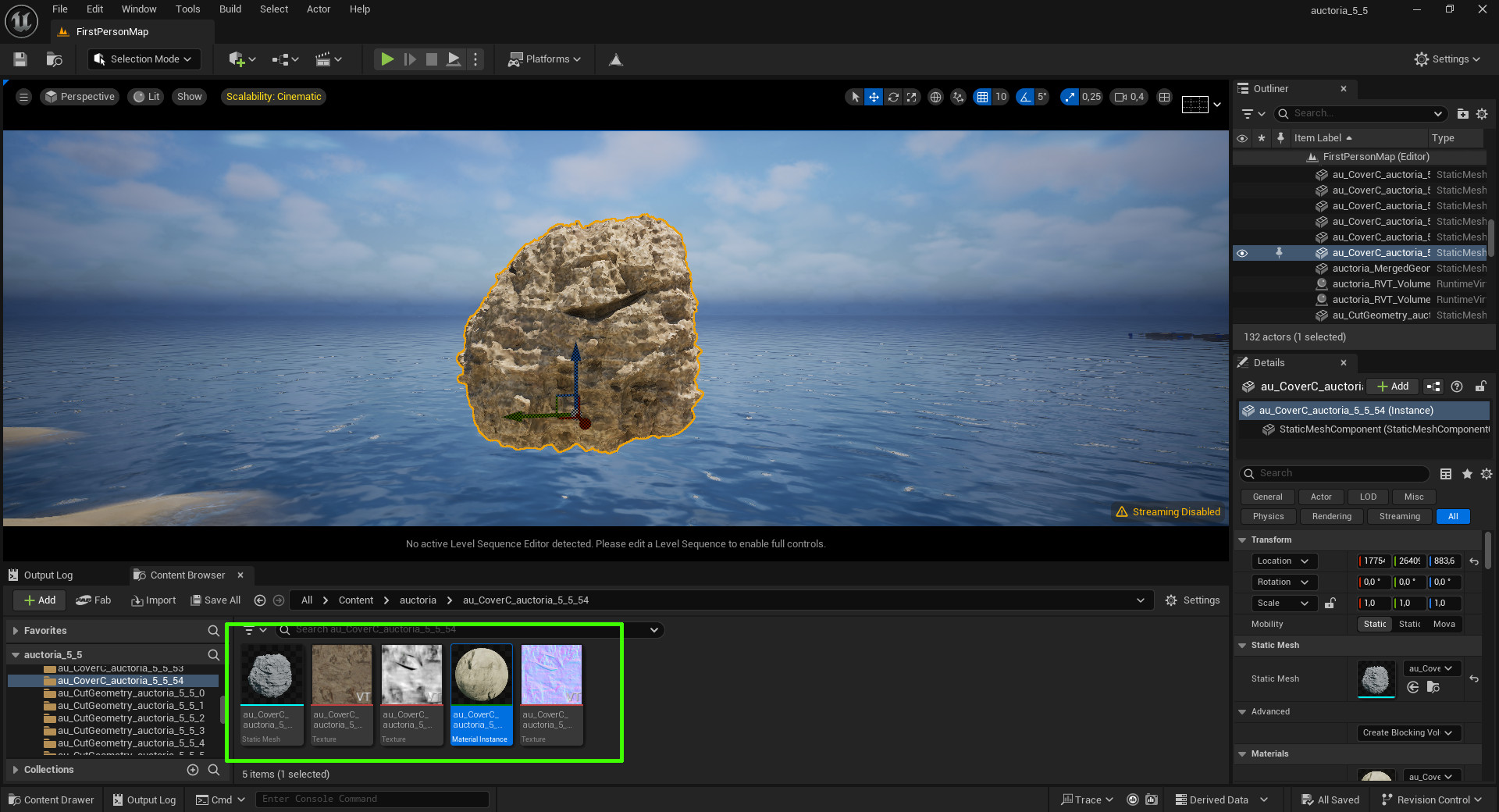
To start building the rock, simply click the BUILD ROCK button using the default settings. After a while you will get a built object, which will consist of an object mesh with material and textures.
¶ Tools Panel
The Tools Panel is organized into the following categories (sections): Shapes, Shape Tools, Simulations, Methods, Filters, Generator.
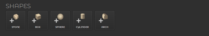
¶ Shapes
The Shapes Section contains basic objects (geometries) that you can use to define the general shape of your rock. Clicking any button on the section below will add the corresponding object to the scene in Unreal Engine.
¶ Shape Tools
The Tools Section contains utilities that make it easy to work with basic objects and build more complex shapes.
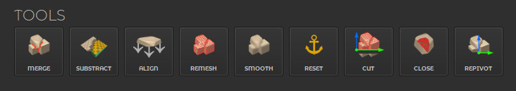
A detailed description of the Shape Tools is provided in a separate section titled In-Depth Overview of Shape Tools.
¶ Simulations
The Simulations Section includes more advanced algorithms designed to simulate natural processes. In the case of rocks, this refers to the simulation of a Rock Joint, discussed in a separate section titled Rock Joint Simulation.

¶ Methods
The Methods Section includes buttons for inserting objects that serve both as a preview and as a definition of the generation method. For rocks, the available Cover Method allows you to add a surface overlay to the object. In the future, additional methods may be introduced, such as Cover Height, which will enable the creation of rocks with a higher triangle count and improved visual quality.

¶ Filters
Filters are basic tools for making minor adjustments to the results produced by the Generator. A detailed description of the filters is provided in a separate section titled In-Depth Overview of Filters.
¶ Generator Section
In the Rocks tab, the Generator Section includes a single Generator responsible for creating the final geometry of the rock sample.

¶ In-Depth Overview of Shape Tools
This section provides a detailed explanation of the Shape Tools available in the Tools Panel.
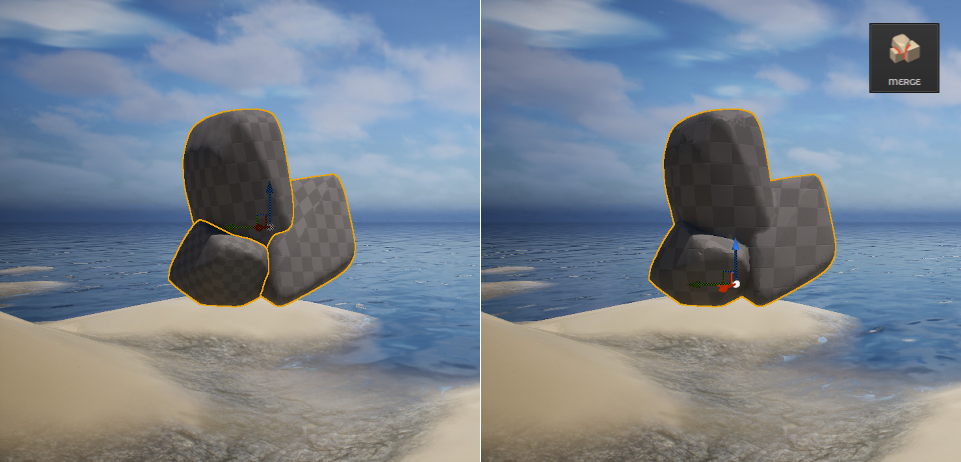
¶ Merge
Merge allows you to combine multiple selected shapes into a single object, making it easier to manage and modify complex structures as one unified mesh. To select multiple objects, hold the left Shift key and click on the objects you want to merge. It is recommended to Reset object transformations before merging objects.
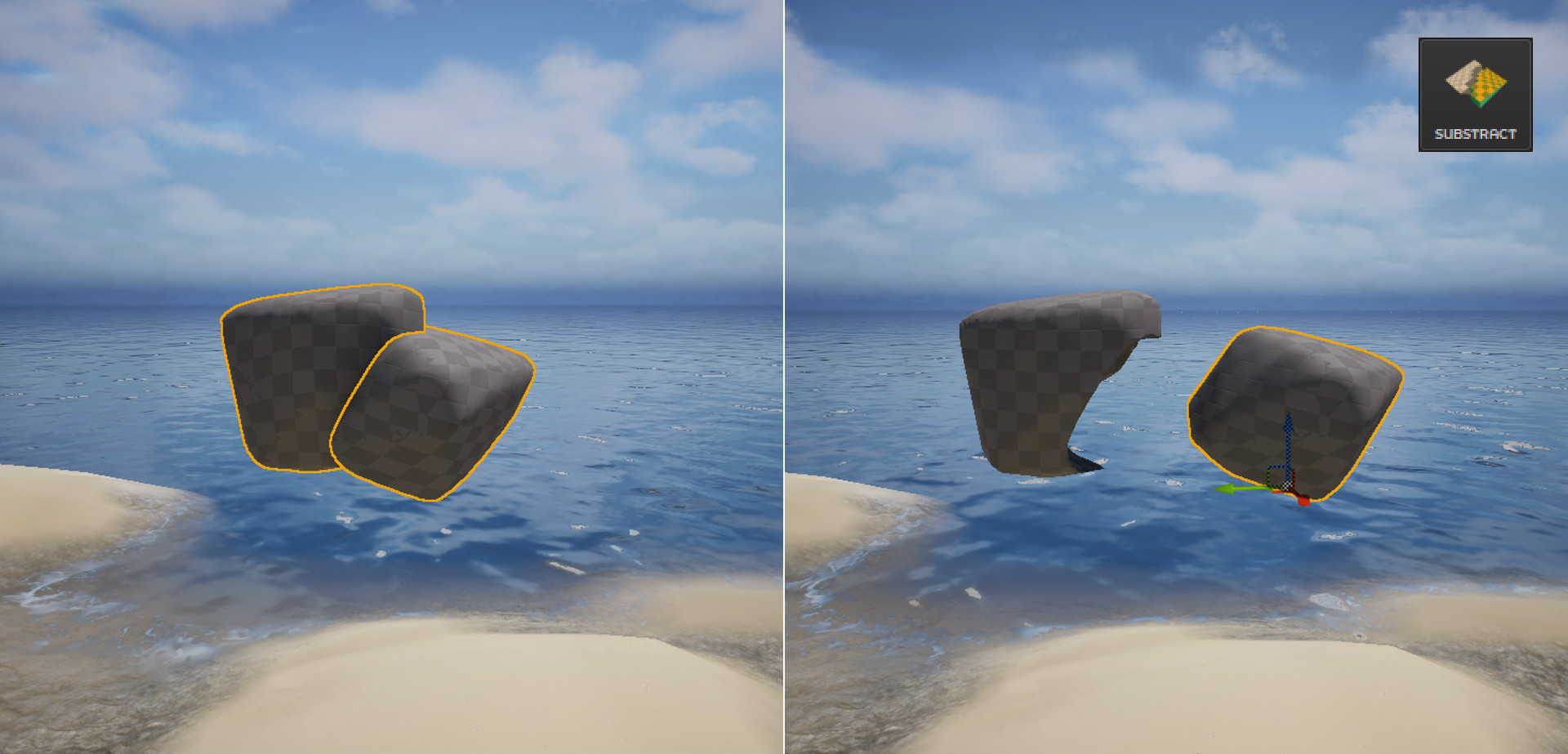
¶ Substract
Substract allows you to cut away parts of one object using the shape of another. The first selected object will be subtracted, and the second one will act as the cutter. To perform the operation, select the object you want to subtract first, then hold the left Shift key and click on the object you want to subtract with. It is recommended to Reset object transformations before using Substract.
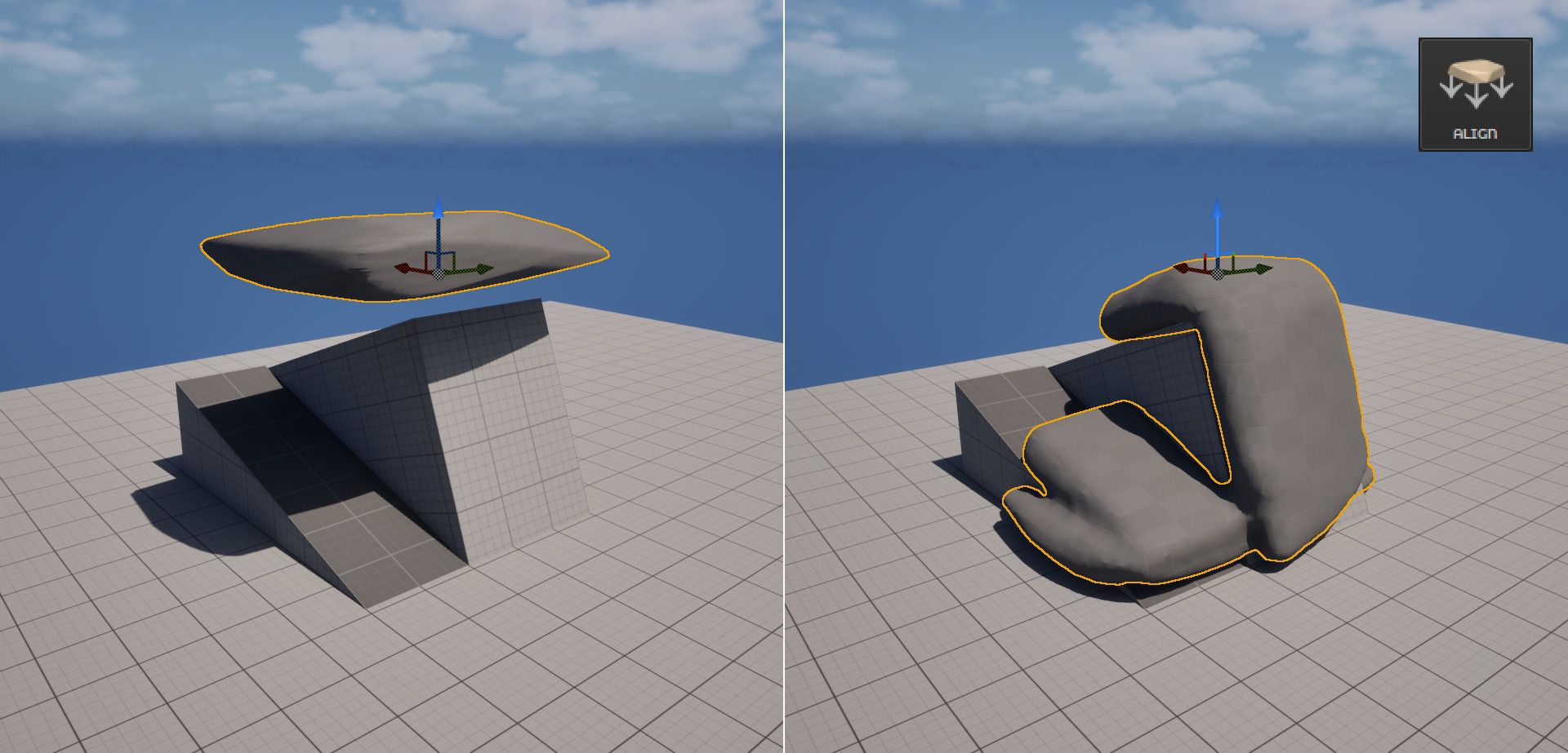
¶ Align
Align works like modeling clay dropped onto a surface, making it possible to simulate soft materials or rocks that conform to the shape of the ground. It is recommended to Reset object transformations before using Align.
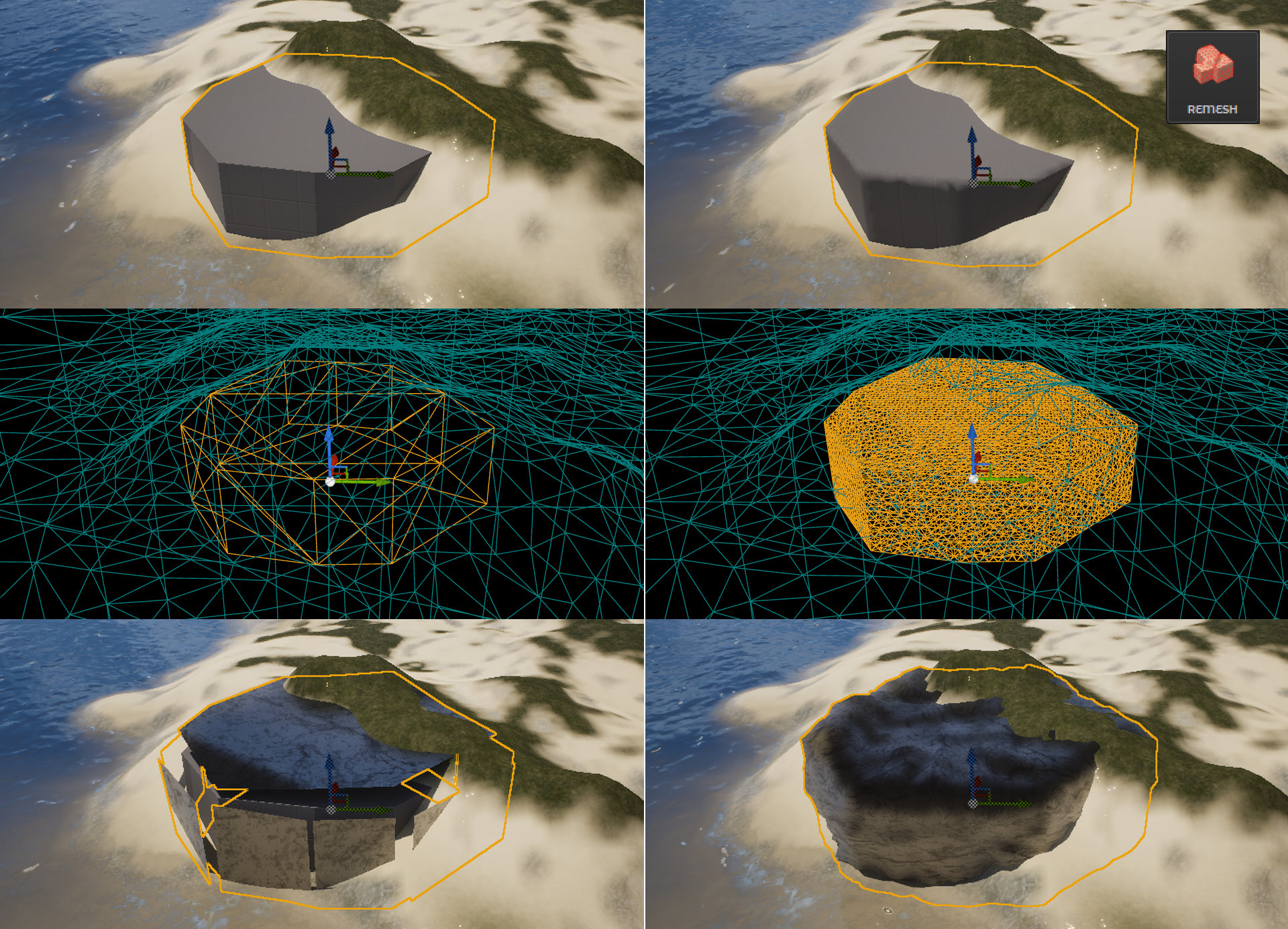
¶ Remesh
Remesh is used to increase the mesh density of a selected object by redistributing its geometry into a more uniform grid. This is especially useful before using the Cover Method, as it ensures a smoother and more accurate visual result. Applying Remesh helps avoid artifacts and improves the appearance of materials during AI-based generation.
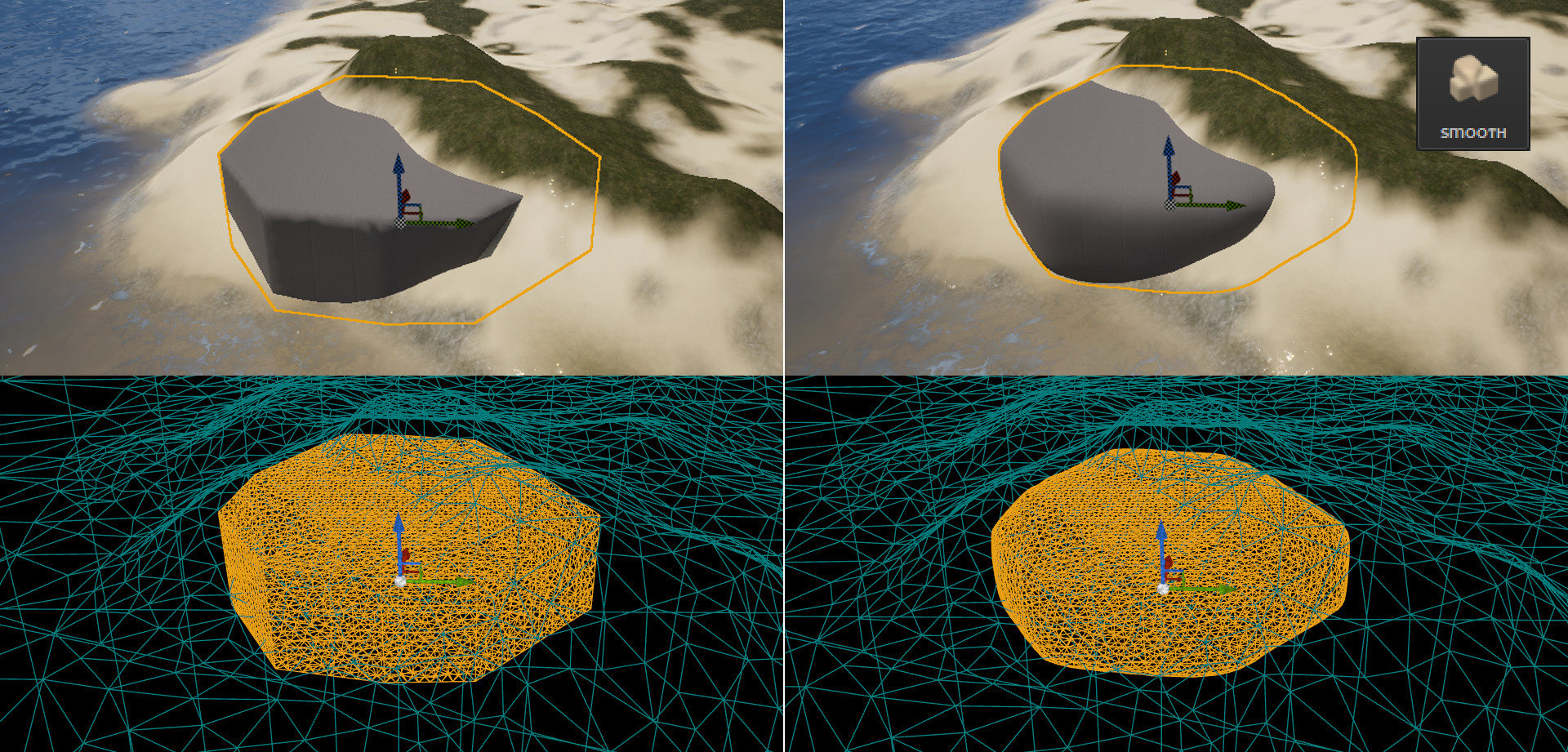
¶ Smooth
Smooth is a tool that softens the surface of a mesh by averaging the positions of vertices, reducing sharp edges and irregularities. It helps create more natural and flowing shapes by smoothing out rough geometry while preserving the overall form. This tool functions similarly to smoothing tools found in standard 3D modeling software. It is recommended to use the Remesh function before applying Smooth to achieve the best results.
¶ Reset Transformation
Reset resets the rotation and scale of the selected object to their default values (rotation: 0°, scale: 1.0 on all axes), without changing its position in the scene. This ensures that shapes behave predictably during operations like Merge or Substract. It is especially useful for maintaining clean and consistent geometry during modeling workflows.
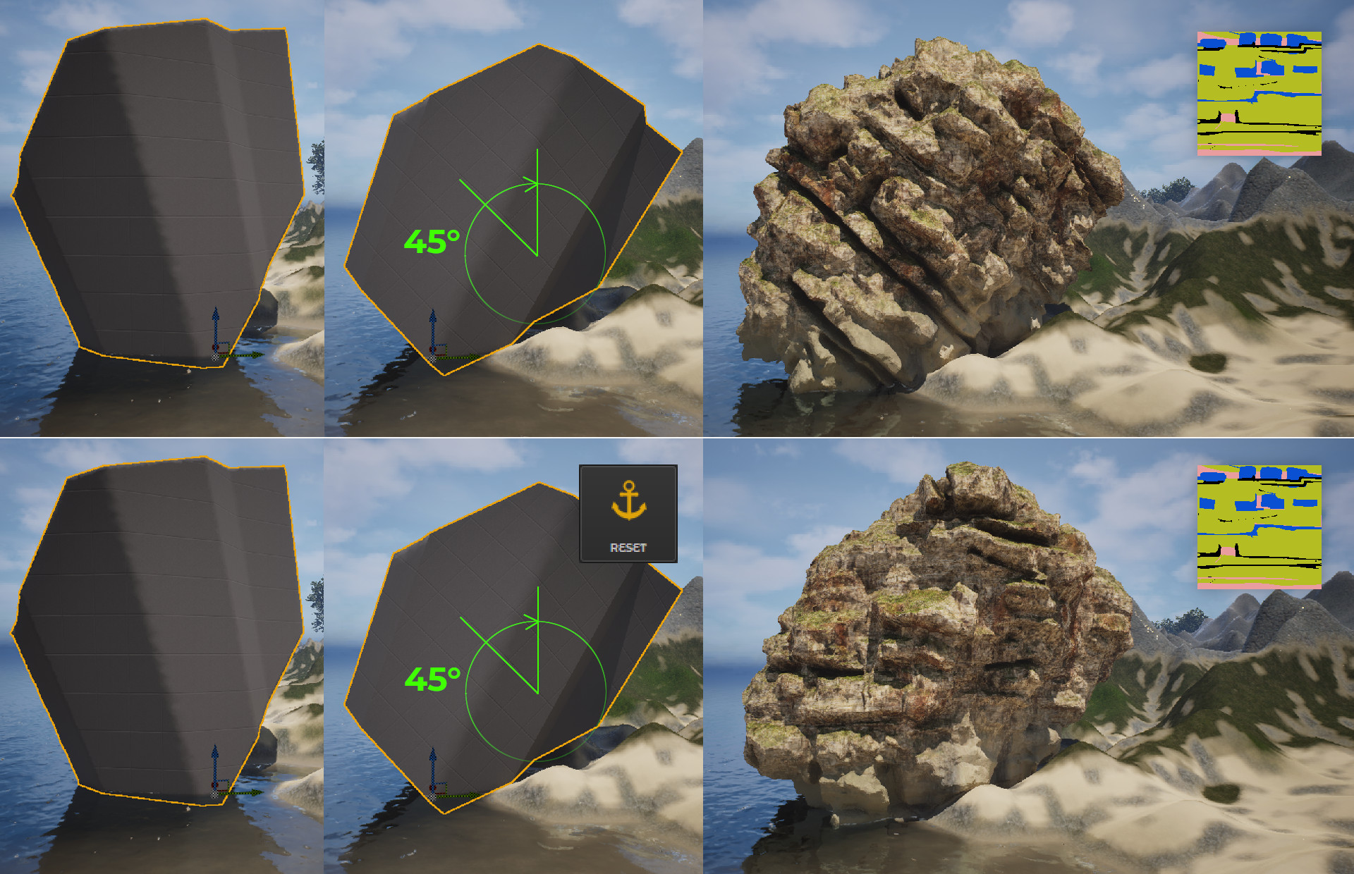
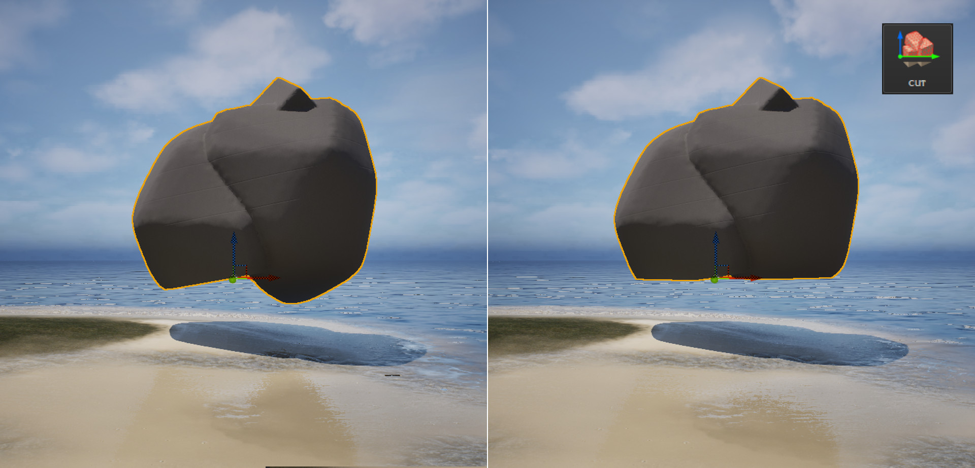
¶ Cut
Cut removes all mesh geometry positioned below the pivot point on the Z axis, effectively slicing the object at that reference level. Removing geometry below the Z-level may result in holes or gaps in the mesh (especially after using the Reset operation). To address this, you can either slightly adjust the angle after resetting, or use the Close tool to fill the resulting holes. The Cover Method works best with closed objects. If the mesh has holes, it will try to fill them based on the curvature of the generated cover geometry.
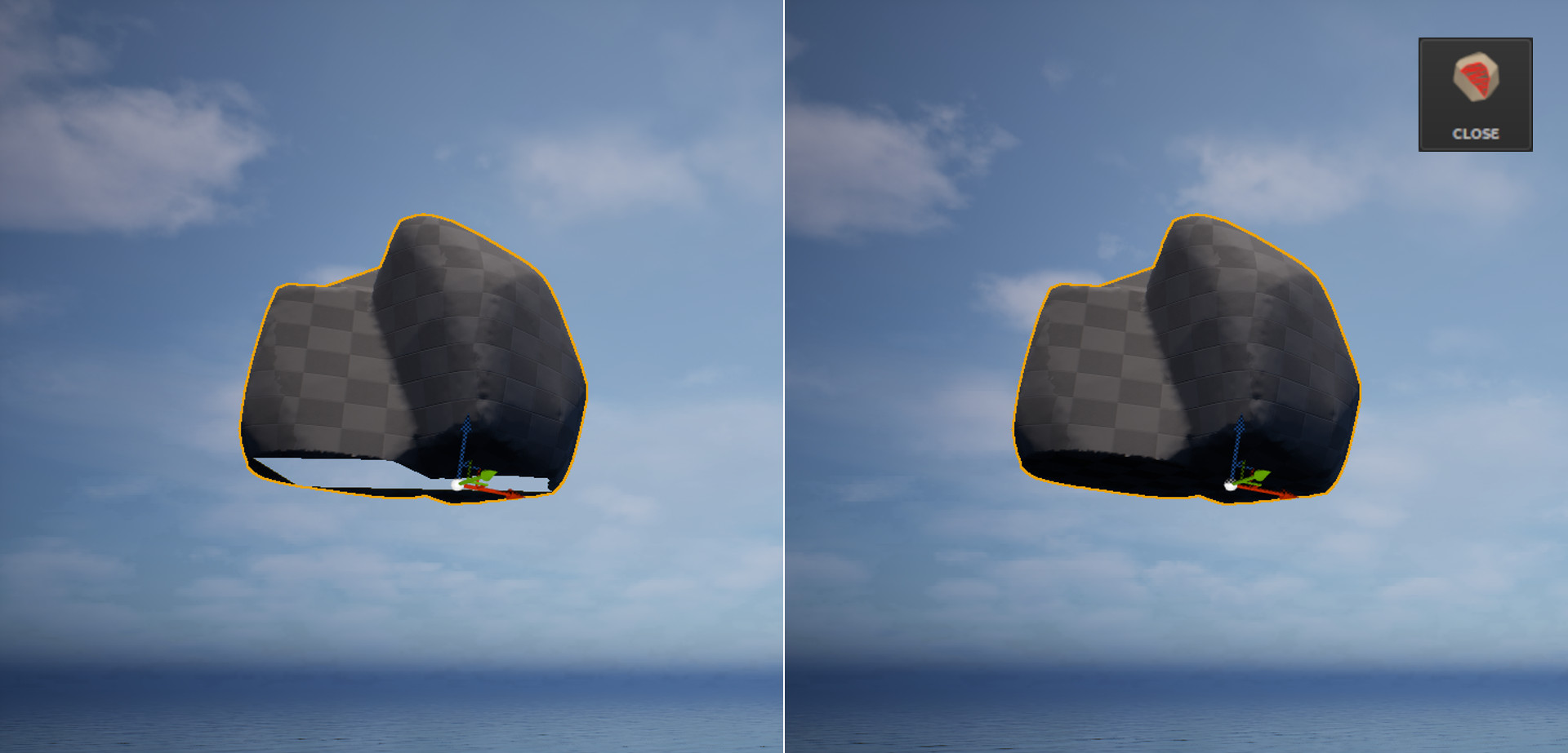
¶ Close (Fill)
Closing (or Fill Holes) fills gaps in the mesh by generating new polygons over open edges. It is useful for restoring watertight geometry after trimming, cutting, or importing incomplete models. The Cover Method works best with closed objects. If the mesh has holes, it will try to fill them based on the curvature of the generated cover geometry.
¶ Repivot
Repivot is a tool for automatically placing the pivot point of a 3D object at its bottom-center position.
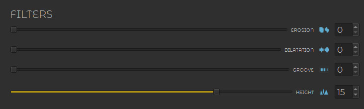
¶ In-Depth Overview of Filters
All filters, except the Height filter, need to be re-generated (REGENERATE button) if you want to make changes. Filters allow for fast, small-scale corrections and should be applied with low values to avoid overprocessing. The filters include: Erosion, Dilatation, Groove and Height.
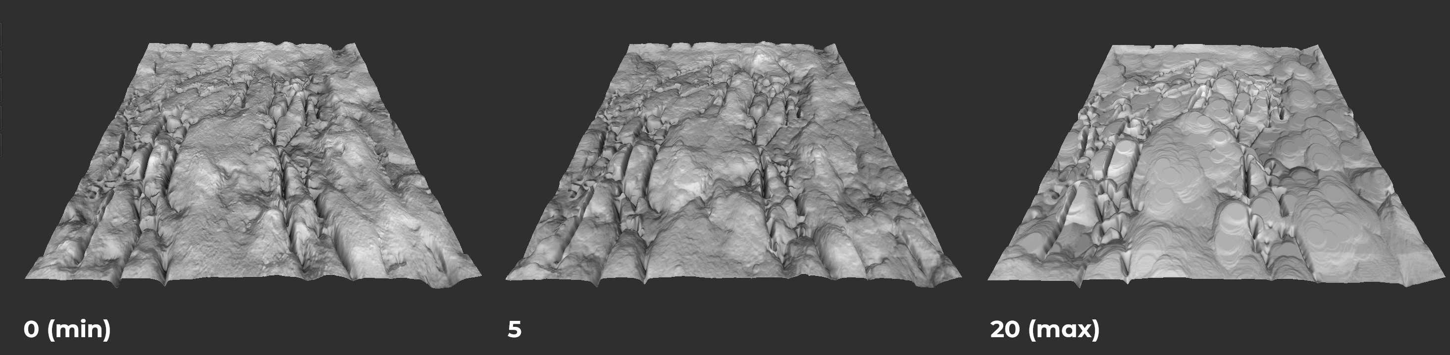
¶ Erosion
Erosion acts like a gentle sculpting tool for rock surfaces, subtly wearing down sharp edges and irregularities to create a more natural and weathered appearance. Keep in mind, however, that it functions as a visual filter rather than a physically accurate simulation—setting it too high may produce unrealistic or undesirable results.
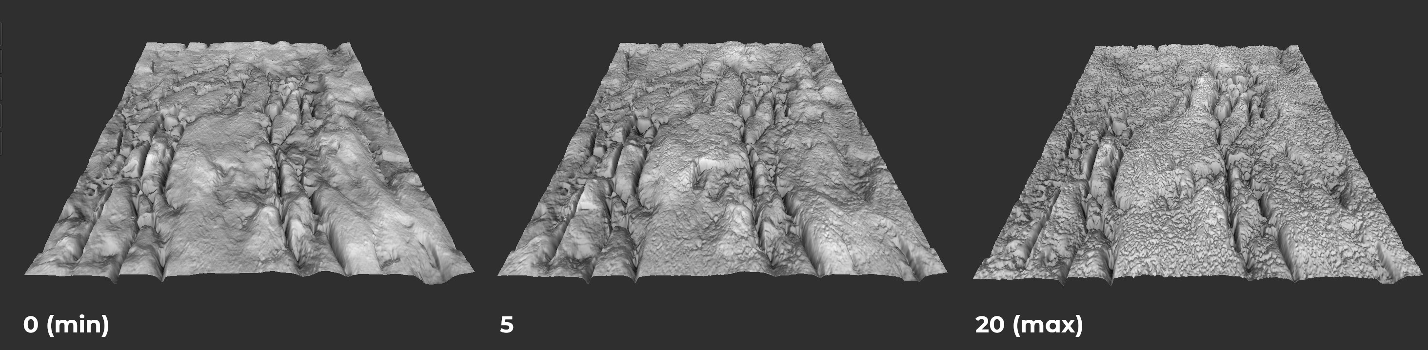
¶ Dilatation
Dilation acts like a subtle outward swelling of rock structures—making formations appear bulkier and more defined, as if the rock has expanded slightly. It enhances the visual presence of rocky features, but keep in mind that this is a filter, not a true geological simulation. Excessive dilation can cause fine details to blur or merge, reducing the overall sharpness of the rock surface.
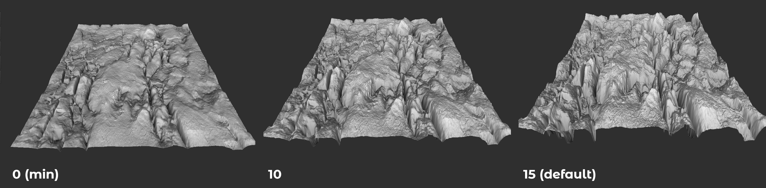
¶ Groove
Groove functions like carving into the rock surface—accentuating natural cracks, furrows, and depressions as if they were deliberately chiseled out. It deepens existing indentations in the rock, making them appear sharper and more pronounced, similar to enhancing the visibility of crevices or erosion lines. While it adds dramatic detail, remember that it's a stylistic filter, not a simulation of real geological erosion.
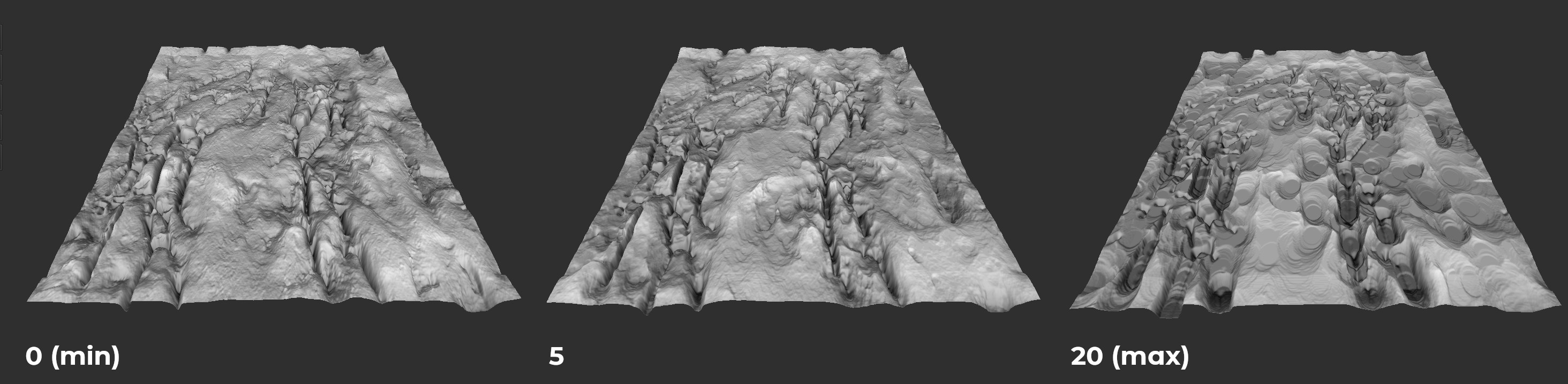
¶ Height
Height controls how much the surface of the rock expands outward, making all details and features rise away from the base shape.
¶ In-Depth Overview of Simulations
Simulations play a key role in shaping realistic and natural-looking rock formations. Unlike simple filters or manual sculpting, simulations attempt to mimic real-world physical processes that affect how rocks form, break, and erode over time. This results in more believable structures and organic surface details. The current version of the plugin enables the simulation of segment maps, i.e., simulations performed before generating the rock sample (using the REGENERATE button).
¶ Rock Joint Simulation
Rock Joint Simulation refers to the process of digitally recreating the natural fractures and separations found in rock formations. The rock joint simulation is performed on the segment map and requires painting sample elements that make up the rock sample, as shown in the figure below.
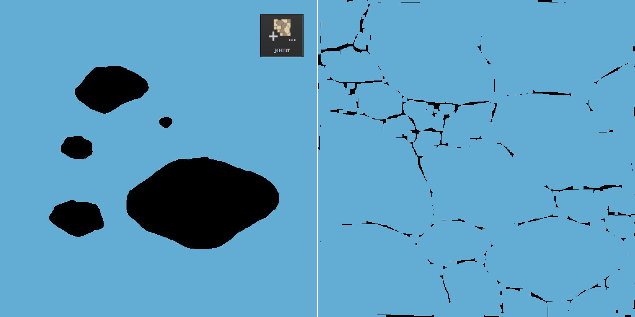
As shown in the figure above, the new segment map is filled with painted elements densely packed across the entire area. The joints are not painted with full continuity, leaving some room for the AI to interpret and complete the structure. You can use any colors, but black is intended for defining clear joints, while the main rock segment will adopt the dominant color. If multiple colors are used, only the most dominant one will be kept.
¶ Build Options
In the Rock Build options, there are several settings (see Fig. 3): Quality, Sharpen Smooth, Sharpen Crease, and Material, which will be discussed in more detail in the following sections.
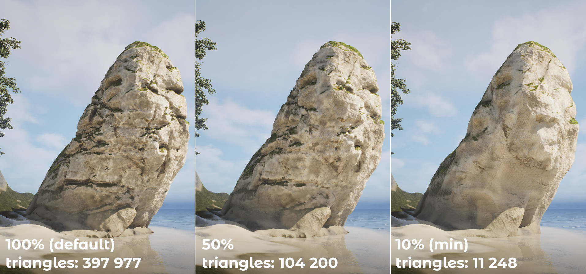
¶ Quality
The Quality parameter is essentially the choice of the number of triangles that the rock will be made of. Setting the Quality to 100% means that the maximum number of triangles can be around 0.5 million triangles.
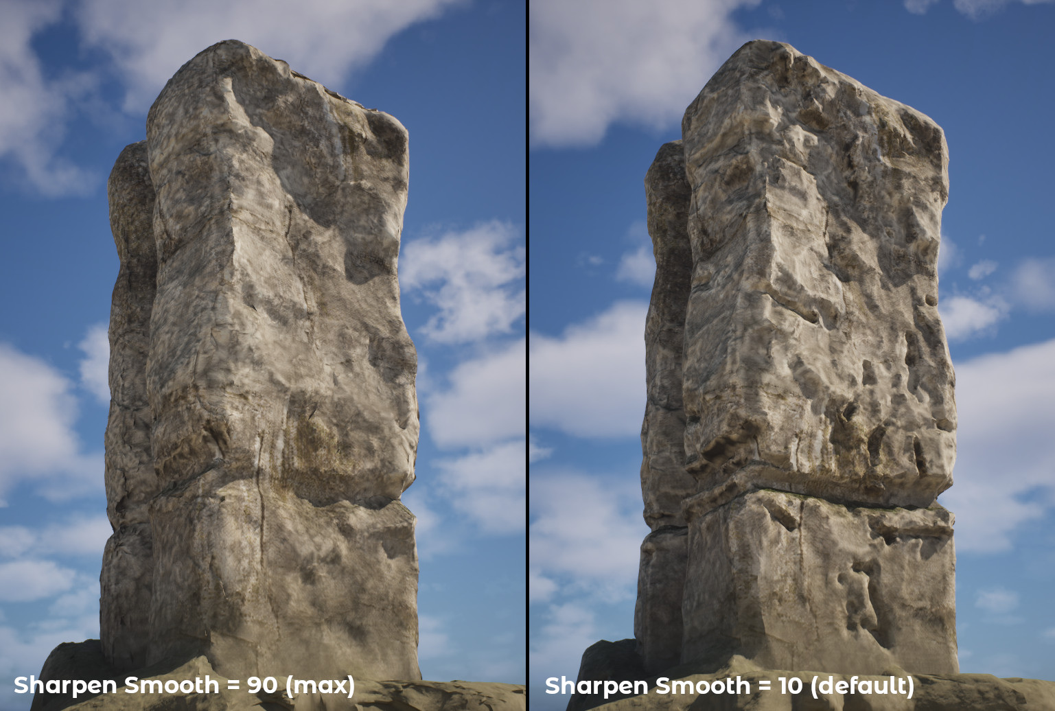
¶ Sharpen Smooth
Sharpen Smooth reduces surface irregularities by smoothing the mesh while preserving sharp edges. It improves the overall shape without rounding out key features, making it useful for cleaning up geometry without losing form.
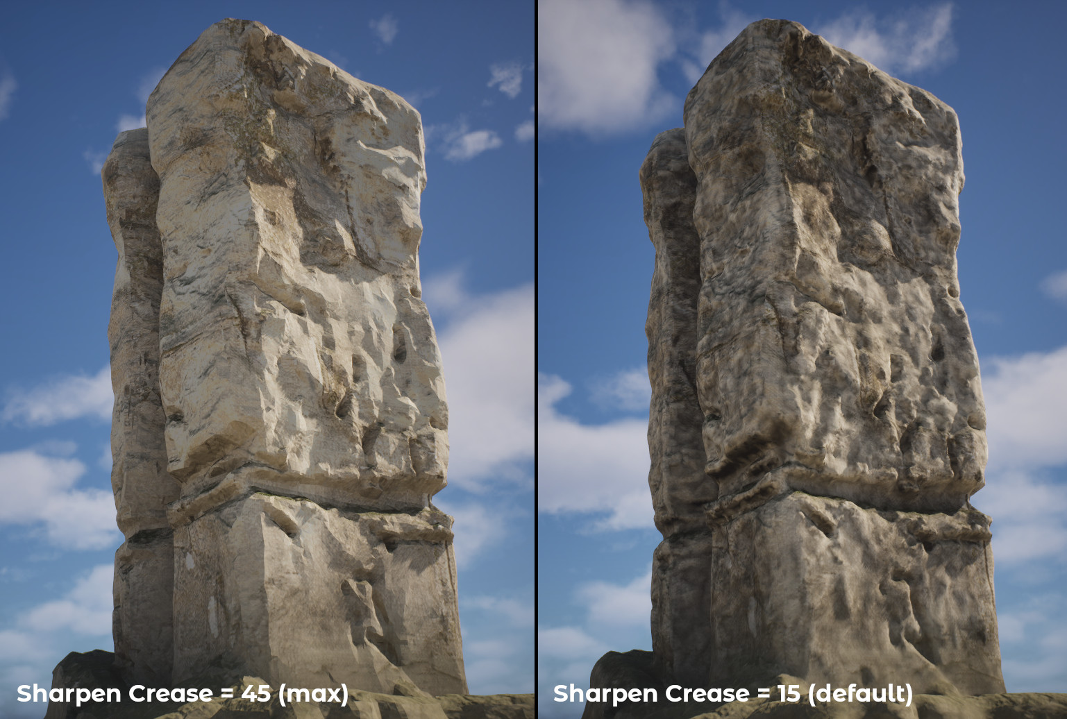
¶ Sharpen Crease
Sharpen Crease Enhances sharp features in rock geometry by locally modifying the mesh along high-contrast surface transitions. This operation reinforces existing edges, cracks, and stratified formations without introducing new topology. It’s particularly useful in rock generation workflows for emphasizing geological details such as fractured lines, erosion breaks, or stylized cuts, resulting in a more distinct and natural appearance.
¶ Material
The Material parameter (enabled by default) determines whether textures and a material should be generated for the created rock. For performance reasons, it is not recommended to generate a new material every time for the same rock type. The best practice is to generate the material once and reuse it for other rocks of the same kind. The next section provides a more detailed description of the key elements of the Rock Material.
¶ Detailed Overview of Rock Material
After generating the rock, you will find textures and a Rock Material (shader) in its main folder, which may require manual adjustments. Below is a detailed description of the material parameters.
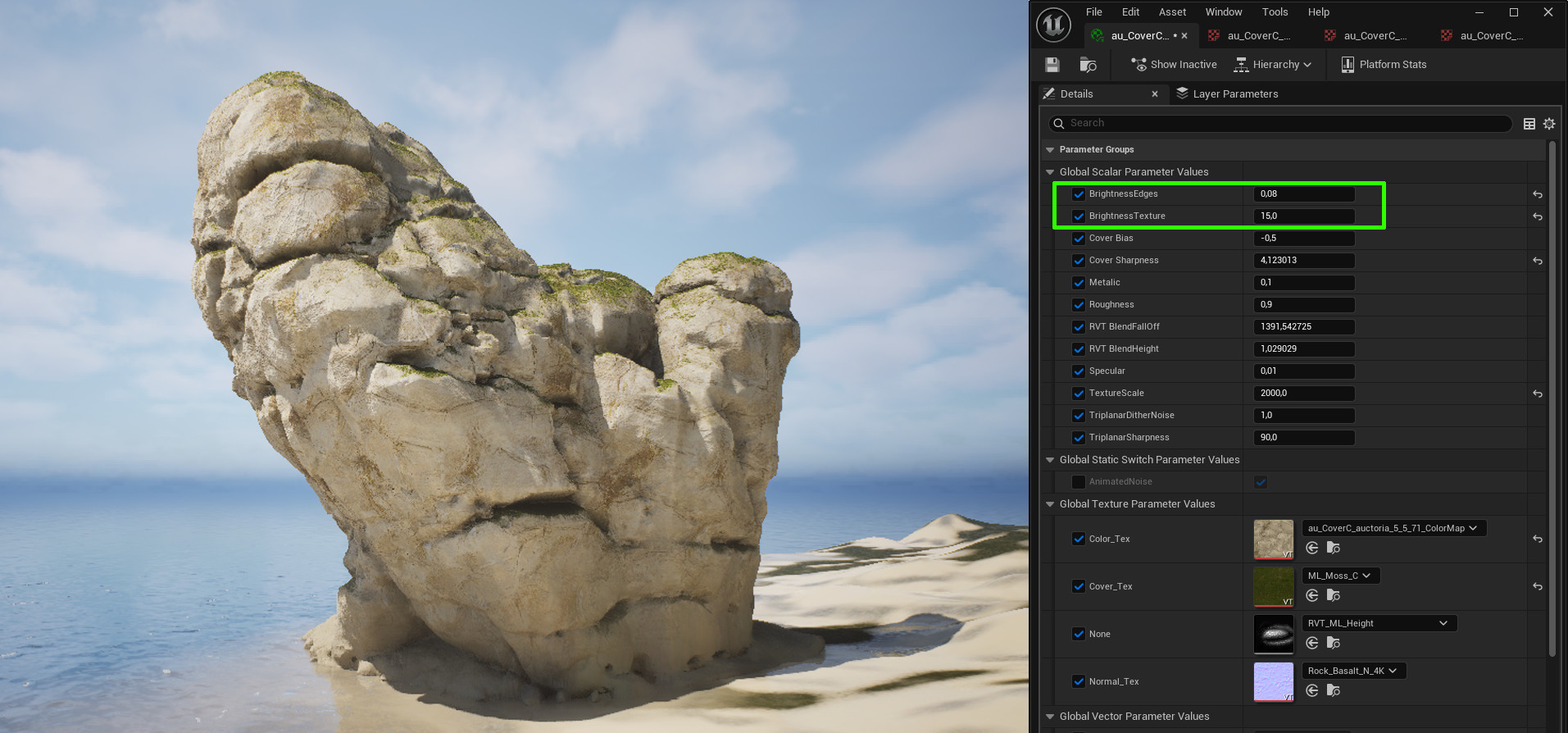
¶ Brightness
Brightness Edges and Brightness Texture are parameters that affect the brightness of the texture and edges, simulating naturally worn rock edges. Naturally, the limestone rock (shown in the figure) appears more realistic without worn edges, but the final choice of parameters is up to you.
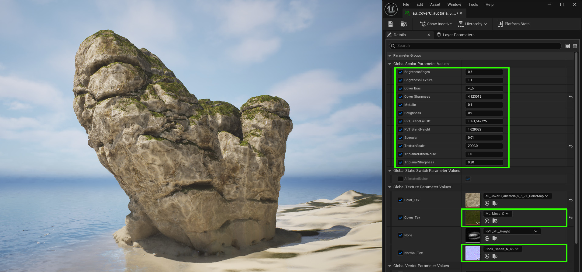
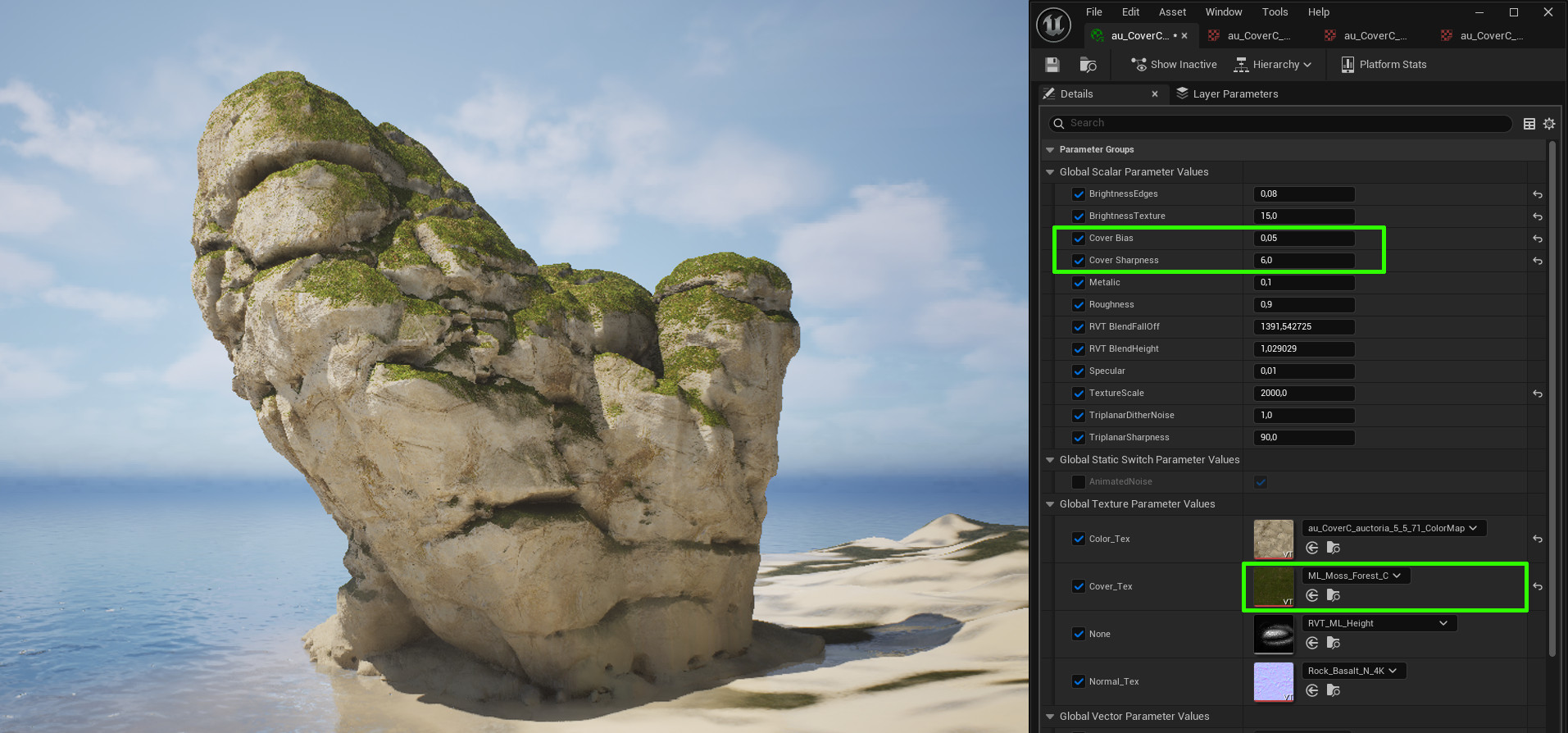
¶ Cover
The Cover Bias and Cover Sharpness parameters control the size of the area covered by an additional texture (e.g., moss, sand) and the sharpness of the transition between textures. A practical approach is to use one of the textures (Cover_Tex) previously generated for the Terrain—this ensures better visual integration of the rocks with their surroundings.
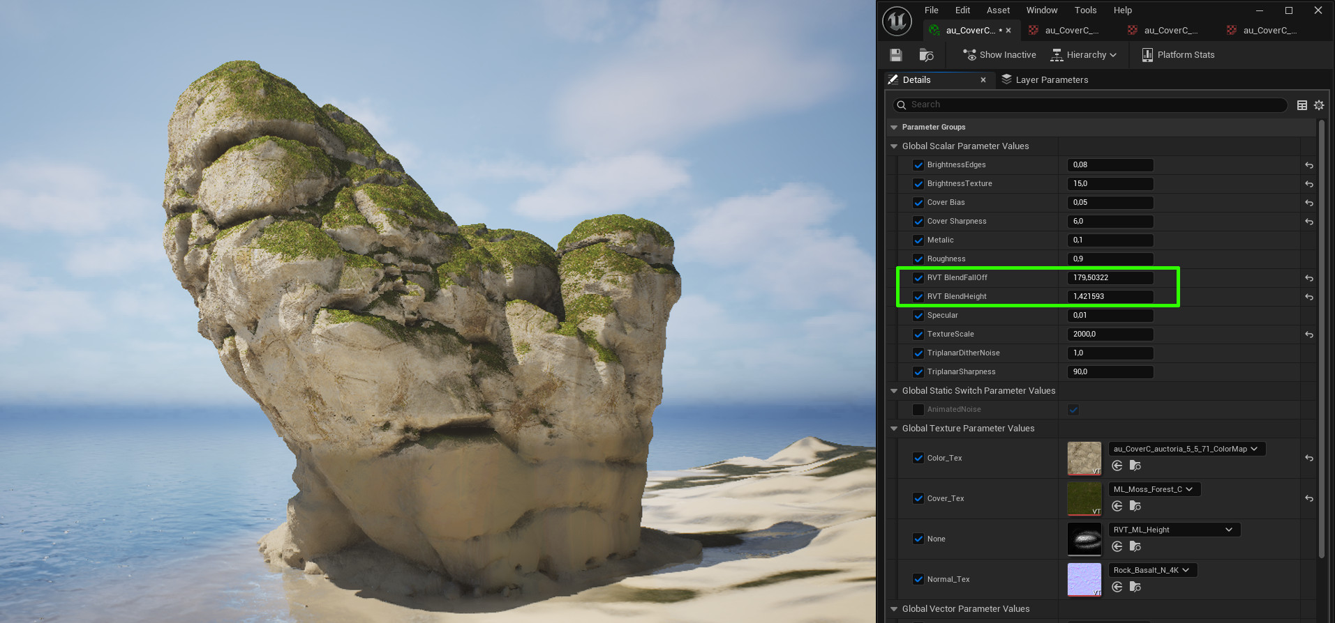
¶ RVT Blending
RVT Blending works on Rocks when this technique has been prepared for the Terrain (see Terrain RVT Blending) and included in the main Rock Base Material, as shown below.
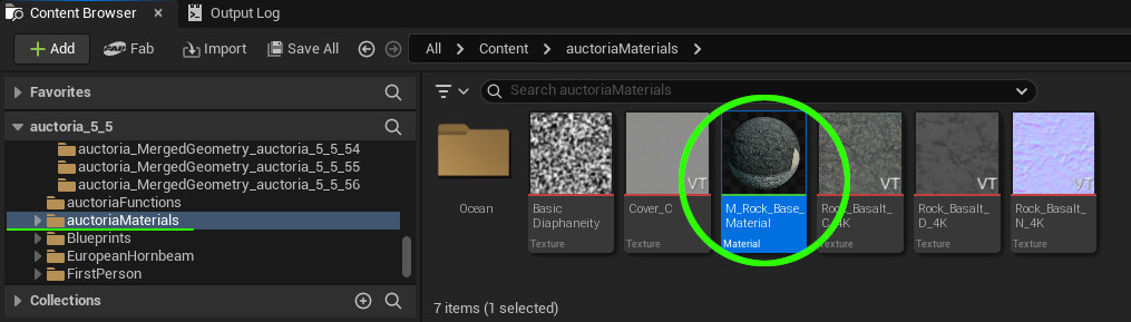
If the connections in your Rock Base Material do not match the setup shown in the figure below, try setting them up manually.
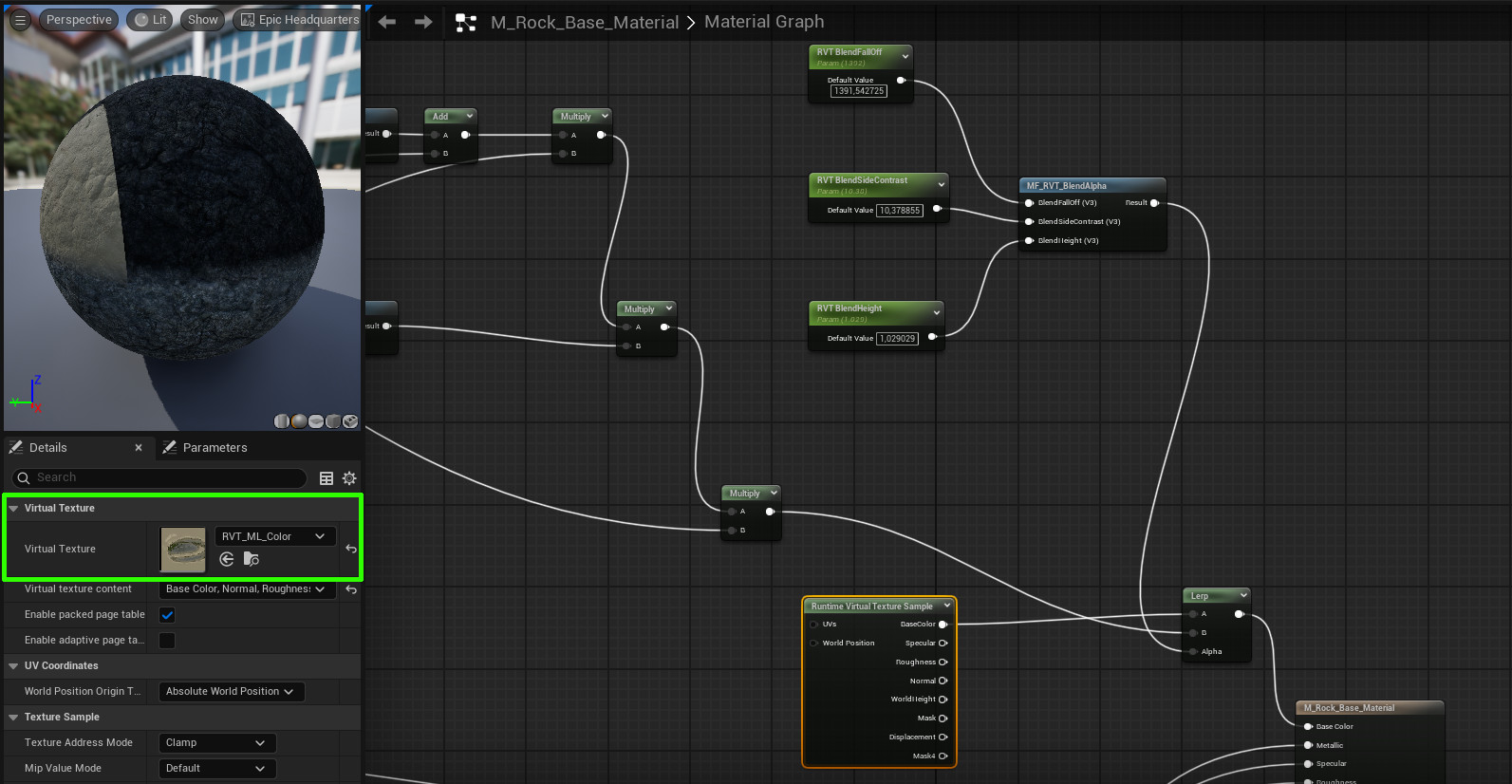
RVT Blending parameters allow you to control the smoothness or sharpness of the transition from terrain texture to rock texture, as well as the height on the rock surface at which this blending occurs.
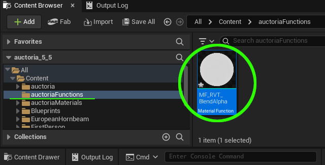
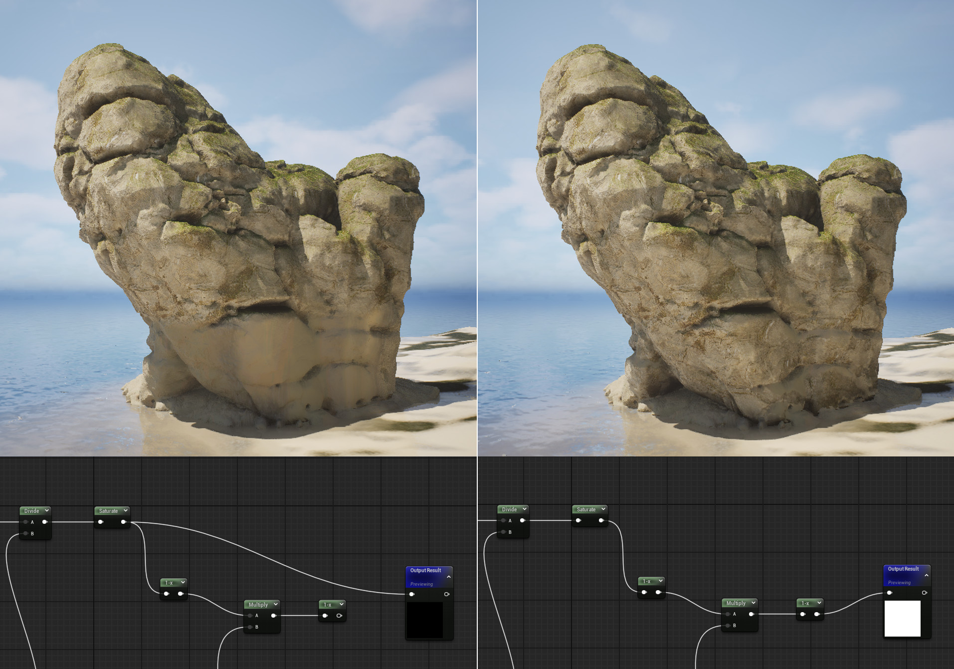
The type of RVT blending is controlled by the RVT_BlendAlpha function (as shown below).
Small changes to the RVT_BlendAlpha function allow you to modify the blending behavior — on the left side of the image below, a continuous transition is shown, while on the right, blending is restricted to horizontal surfaces only.
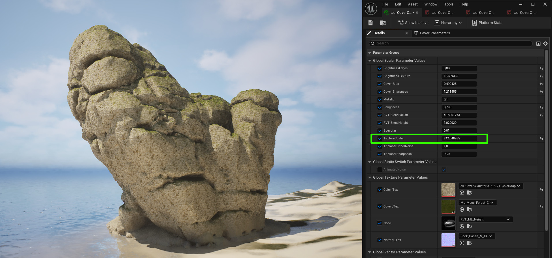
¶ Texture Scale
The Texture Scale parameter affects the tiling of the texture on the object and depends on the size of the generated rock. Try to set the scale so that texture repetitions are as unnoticeable as possible.
¶ ⚠️ Note on the Final Look
When showcasing the final result, remember that rocks appear more natural and realistic when presented in natural surroundings, such as near vegetation and trees. If you display the rock alone, it might look like a toy or a 3D print. A good practice is to modify or completely replace the normal map (Normal_Text) at the final stage to enhance realism. By default, the normal map is generated and matched to the semantics of the color texture, so changing it can increase the level of detail. This approach is commonly used in 3D graphics — the normal map can be enhanced or modified to achieve a more detailed and visually appealing final result.